Capacitor
The capacitor is a component which has the ability or “capacity” to store energy in the form of an electrical charge producing a potential difference (Static Voltage) across its plates, much like a small rechargeable battery.
There are many different kinds of capacitors available from very small capacitor beads used in resonance circuits to large power factor correction capacitors, but they all do the same thing, they store charge.
In its basic form, a capacitor consists of two or more parallel conductive (metal) plates which are not connected or touching each other, but are electrically separated either by air or by some form of a good insulating material such as waxed paper, mica, ceramic, plastic or some form of a liquid gel as used in electrolytic capacitors. The insulating layer between a capacitors plates is commonly called the Dielectric.

A Typical Capacitor
Due to this insulating layer, DC current can not flow through the capacitor as it blocks it allowing instead a voltage to be present across the plates in the form of an electrical charge.
The conductive metal plates of a capacitor can be either square, circular or rectangular, or they can be of a cylindrical or spherical shape with the general shape, size and construction of a parallel plate capacitor depending on its application and voltage rating.
When used in a direct current or DC circuit, a capacitor charges up to its supply voltage but blocks the flow of current through it because the dielectric of a capacitor is non-conductive and basically an insulator. However, when a capacitor is connected to an alternating current or AC circuit, the flow of the current appears to pass straight through the capacitor with little or no resistance.
Testing the Capacitor?
Determining the value a capacitor has can be accomplished in a few ways. Number one, of course, is a marking on the capacitor itself.
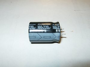
This particular capacitor has a capacitance of 220μF (micro farad) with a tolerance of 20%. This means that is could be anywhere between 176μF and 264μF. It has a voltage rating of 160V. The arrangement of the leads all show that it is a radial capacitor. Both leads exit on one side versus an axial arrangement where one lead exits from either side of the capacitors body. Also, the arrowed stripe on the side of the capacitor indicates the polarity, the arrows are pointing towards the negative pin.
Now the main question here is, how to check a capacitor to see if it needs replacing.
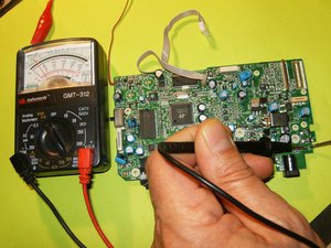
To perform a check on a capacitor while it is still installed in a circuit, an ESR meter will be necessary. If the capacitor is removed from the circuit then a multimeter set as an ohm meter can be used, but only to perform an all-or-nothing test. This test will only show if the capacitor is completely dead, or not. It will not determine if the capacitor is in good or poor condition. To determine if a capacitor is functioning at the right value (capacitance), a capacitor tester will be necessary. Of course, this also holds true to determine the value of an unknown capacitor.
The meter used for this Wiki is the cheapest one available at any department store. For these test it is also advisable to use an analog multimeter. It will show the movement in a more visual way than a digital multimeter that only display rapidly changing numbers. This should enable anybody to perform these tests without spending a fortune on something like a Fluke meter.
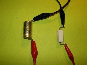
Always discharge a capacitor before testing it, it will be a shocking surprise if this does not get done. Very small capacitors can be discharged by bridging both leads with a screw driver. A better way of doing it would be by discharging the capacitor through a load. In this case alligator cables and a resistor will accomplish this. Here is a great site showing how to construct a discharge tools.
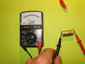
To test the capacitor with a multimeter, set the meter to read in the high ohms range, somewhere above 10k and 1m ohms. Touch the meter leads to the corresponding leads on the capacitor, red to positive and black to negative. The meter should start at zero and then moving slowly toward infinity. This means that the capacitor is in working condition. If the meter stays at zero, the capacitor is not charging through the battery of the meter, meaning it is not working.
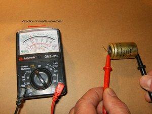
This will also work with SMD caps. Same test with the needle of the multimeter moving slowly in the same direction.
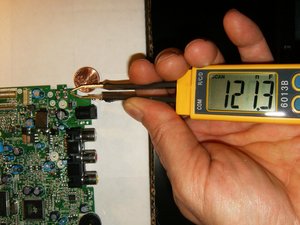
One more test that one can do on a capacitor is a voltage test. We know that capacitors store a potential difference of charges across their plate, those are voltages. A capacitor has an anode which has a positive voltage and a cathode which has a negative voltage. One way to check if a capacitor is working is to charge it up with a voltage and then read the voltage across the anode and cathode. For this it is necessary to charge the capacitor with voltage, and to apply a DC voltage to the capacitor leads. In this case polarity is very important. If this capacitor has a positive and negative lead, it is a polarized capacitors (electrolytic capacitors). Positive voltage will go to the anode, and negative goes to the cathode of the capacitor. Remember to check the markings on the capacitor to be tested. Then apply a voltage, which should be less than the voltage the capacitor is rated for, for a few seconds. In this example the 160V capacitor will be charged with a 9V DC battery for a few seconds.

After the charge is finished, disconnect the battery from the capacitor. Use the multimeter and read the voltage on the capacitor leads. The voltage should read near 9 volts. The voltage will discharge rapidly to 0V because the capacitor is discharging through the multimeter. If the capacitor will not retain that voltage, it is defective and should be replaced.
The easiest of course will be to check a capacitor with a capacitance meter. Here is a FRAKO axial GPF 1000μF 40V with a 5% tolerance. Checking this capacitor with a capacitance meter is straight forward. On these capacitors, the positive lead is marked. Attach the positive (red) lead from the meter to that and the negative (black) to the opposite. This capacitor shows 1038μF, clearly within its tolerance.

To test an SMD capacitor may be difficult to do with the bulky probes. One can either solder needles to the end of those probes, or invest in some smart tweezers. The preferred way would be using smart tweezers.
Some capacitors do not require any test to determine failure. If a visual inspection of the capacitors reveal any sign of bulging tops, those need to be replaced. This is the most common failure in power supplies. When replacing a capacitor, it is of utmost importance to replace it with a capacitor of the same, or higher value. Never subsidize with a capacitor of lesser value.

If the capacitor that is going to be replaced or checked, does not have any markings on it, a schematic will be necessary. The image below from here shows a few symbols for capacitors that are used on a schematic.

No comments:
Post a Comment