Saturday, August 25, 2018

DIODE

DIODE

Diode only blocks current in the reverse direction while the reverse voltage is within a limited range otherwise reverse barrier breaks and the diode only blocks current in the reverse direction while the reverse voltage is within a limited range otherwise reverse barrier breaks and the voltage at which this breakdown occurs is called reverse breakdown voltage. The diode acts as a valve in the electronic and electrical circuits. A PN junction is the simplest form of the semiconductor diode which behaves as ideally short circuit when it is in forward biased and behaves as ideally open circuit when it is in the reverse biased. Beside simple PN junction diodes, there are different types of diodes although the fundamental principles are more or less same. So a particular arrangement of diodes can convert AC to pulsating DC, and hence, it is sometimes also called as a rectifier. The name diode is derived from "di - ode" which means a device having two electrodes.

Symbol of Diode

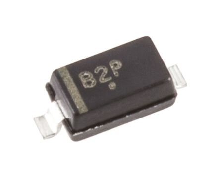
The symbol of a diode is shown below. The arrowhead points in the direction of conventional current flow. Symbol of Diode We can create a simple PN junction diode by doping donor impurity in one portion and acceptor impurity in other portion of silicon or germanium crystal block. These dopings make a PN junction at the middle part of the block beside which one portion becomes p-type (doped with trivalent or acceptor impurity), and another portion becomes n-type (doped with pentavalent or donor impurity). We can also form a PN junction by joining a p-type (intrinsic semiconductor doped with a trivalent impurity) and n-type semiconductor (intrinsic semiconductor doped with a pentavalent impurity) together with a special fabrication technique. Hence, it is a device with two elements, the p-type forms anode, and the n-type forms the cathode. These terminals are brought out to make the external connections. Image result for smt diode
Working Principle of Diode

Unbiased Diode

N-side will have a significant number of free electrons, and very few holes (due to thermal excitation) whereas the p side will have a high concentration of holes and very few free electrons. Due to this, a process called diffusion takes place. In this process free electrons from n side will diffuse (spread) into the p side and recombine with holes present there, leaving positive immobile (not moveable) ions in n side and creating negative immobile ions in the p-type side of the diode.oltage at which this breakdown occurs is called reverse breakdown voltage. The diode acts as a valve in the electronic and electrical circuits. A PN junction is the simplest form of the semiconductor diode which behaves as ideally short circuit when it is in forward biased and behaves as ideally open circuit when it is in the reverse biased. Beside simple PN junction diodes, there are different types of diodes although the fundamental principles are more or less same. So a particular arrangement of diodes can convert AC to pulsating DC, and hence, it is sometimes also called as a rectifier. The name diode is derived from "di - ode" which means a device having two electrodes.

Symbol of DIODE

The symbol of a diode is shown below. The arrowhead points in the direction of conventional current flow. Symbol of Diode We can create a simple PN junction diode by doping donor impurity in one portion and acceptor impurity in other portion of silicon or germanium crystal block. These dopings make a PN junction at the middle part of the block beside which one portion becomes p-type (doped with trivalent or acceptor impurity), and another portion becomes n-type (doped with pentavalent or donor impurity). We can also form a PN junction by joining a p-type (intrinsic semiconductor doped with a trivalent impurity) and n-type semiconductor (intrinsic semiconductor doped with a pentavalent impurity) together with a special fabrication technique. Hence, it is a device with two elements, the p-type forms anode, and the n-type forms the cathode. These terminals are brought out to make the external connections. diode

Working Principle of Diode

Unbiased Diode

N-side will have a significant number of free electrons, and very few holes (due to thermal excitation) whereas the p side will have a high concentration of holes and very few free electrons. Due to this, a process called diffusion takes place. In this process free electrons from n side will diffuse (spread) into the p side and recombine with holes present there, leaving positive immobile (not moveable) ions in n side and creating negative immobile ions in the p-type side of the diode.


Testing of diode

Image result for tick symbol
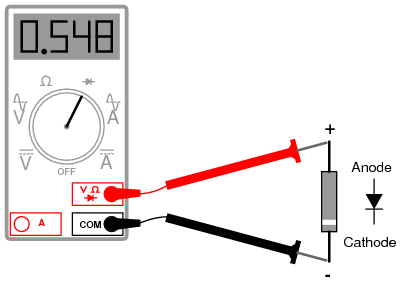
Meter with a “Diode check” function displays the forward voltage drop of 0.548 volts instead of a low resistance.
Determination of diode polarity: (a) Low resistance indicates forward bias, black lead is cathode and red lead anode (for most meters) (b) Reversing leads shows high resistance indicating reverse bias.


Next We can see about Transistor

INDUCTOR

IINDUCTOR


An inductor, also called a coilchoke or reactor, is a passive two terminal component that stores energy in a magnetic field when electric current flows through it. An inductor typically consists of an insulated wire wound into a coil around a core.
When the current flowing through an inductor changes, the time-varying magnetic field induces an electromotive force  (e.m.f.) (Voltage) in the conductor, described by Faraday'sl law o motion. According to Lenz's law the induced voltage has a polarity (direction) which opposes the change in current that created it. As a result, inductors oppose any changes in current through them.

Image result for inductor Image result for smt inductor

Testing a inductor


Inductor can be tested with a continuity test in multimeter

Next we can see about Diode

Capacitor

Capacitor

The capacitor is a component which has the ability or “capacity” to store energy in the form of an electrical charge producing a potential difference (Static Voltage) across its plates, much like a small rechargeable battery.
There are many different kinds of capacitors available from very small capacitor beads used in resonance circuits to large power factor correction capacitors, but they all do the same thing, they store charge.
In its basic form, a capacitor consists of two or more parallel conductive (metal) plates which are not connected or touching each other, but are electrically separated either by air or by some form of a good insulating material such as waxed paper, mica, ceramic, plastic or some form of a liquid gel as used in electrolytic capacitors. The insulating layer between a capacitors plates is commonly called the Dielectric.
introduction to capacitors
A Typical Capacitor
Due to this insulating layer, DC current can not flow through the capacitor as it blocks it allowing instead a voltage to be present across the plates in the form of an electrical charge.
The conductive metal plates of a capacitor can be either square, circular or rectangular, or they can be of a cylindrical or spherical shape with the general shape, size and construction of a parallel plate capacitor depending on its application and voltage rating.
When used in a direct current or DC circuit, a capacitor charges up to its supply voltage but blocks the flow of current through it because the dielectric of a capacitor is non-conductive and basically an insulator. However, when a capacitor is connected to an alternating current or AC circuit, the flow of the current appears to pass straight through the capacitor with little or no resistance.

Testing the Capacitor?

Determining the value a capacitor has can be accomplished in a few ways. Number one, of course, is a marking on the capacitor itself.
Block Image
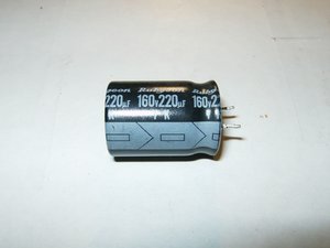
This particular capacitor has a capacitance of 220μF (micro farad) with a tolerance of 20%. This means that is could be anywhere between 176μF and 264μF. It has a voltage rating of 160V. The arrangement of the leads all show that it is a radial capacitor. Both leads exit on one side versus an axial arrangement where one lead exits from either side of the capacitors body. Also, the arrowed stripe on the side of the capacitor indicates the polarity, the arrows are pointing towards the negative pin.
Now the main question here is, how to check a capacitor to see if it needs replacing.
To perform a check on a capacitor while it is still installed in a circuit, an ESR meter will be necessary. If the capacitor is removed from the circuit then a multimeter set as an ohm meter can be used, but only to perform an all-or-nothing test. This test will only show if the capacitor is completely dead, or not. It will not determine if the capacitor is in good or poor condition. To determine if a capacitor is functioning at the right value (capacitance), a capacitor tester will be necessary. Of course, this also holds true to determine the value of an unknown capacitor.
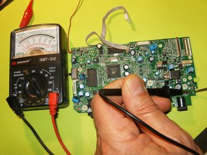
The meter used for this Wiki is the cheapest one available at any department store. For these test it is also advisable to use an analog multimeter. It will show the movement in a more visual way than a digital multimeter that only display rapidly changing numbers. This should enable anybody to perform these tests without spending a fortune on something like a Fluke meter.
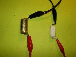
Always discharge a capacitor before testing it, it will be a shocking surprise if this does not get done. Very small capacitors can be discharged by bridging both leads with a screw driver. A better way of doing it would be by discharging the capacitor through a load. In this case alligator cables and a resistor will accomplish this. Here is a great site showing how to construct a discharge tools.
Block Image
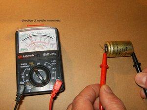
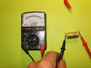
To test the capacitor with a multimeter, set the meter to read in the high ohms range, somewhere above 10k and 1m ohms. Touch the meter leads to the corresponding leads on the capacitor, red to positive and black to negative. The meter should start at zero and then moving slowly toward infinity. This means that the capacitor is in working condition. If the meter stays at zero, the capacitor is not charging through the battery of the meter, meaning it is not working.
Block Image
This will also work with SMD caps. Same test with the needle of the multimeter moving slowly in the same direction.
Block Image
One more test that one can do on a capacitor is a voltage test. We know that capacitors store a potential difference of charges across their plate, those are voltages. A capacitor has an anode which has a positive voltage and a cathode which has a negative voltage. One way to check if a capacitor is working is to charge it up with a voltage and then read the voltage across the anode and cathode. For this it is necessary to charge the capacitor with voltage, and to apply a DC voltage to the capacitor leads. In this case polarity is very important. If this capacitor has a positive and negative lead, it is a polarized capacitors (electrolytic capacitors). Positive voltage will go to the anode, and negative goes to the cathode of the capacitor. Remember to check the markings on the capacitor to be tested. Then apply a voltage, which should be less than the voltage the capacitor is rated for, for a few seconds. In this example the 160V capacitor will be charged with a 9V DC battery for a few seconds.
Block Image
After the charge is finished, disconnect the battery from the capacitor. Use the multimeter and read the voltage on the capacitor leads. The voltage should read near 9 volts. The voltage will discharge rapidly to 0V because the capacitor is discharging through the multimeter. If the capacitor will not retain that voltage, it is defective and should be replaced.
Block Image
The easiest of course will be to check a capacitor with a capacitance meter. Here is a FRAKO axial GPF 1000μF 40V with a 5% tolerance. Checking this capacitor with a capacitance meter is straight forward. On these capacitors, the positive lead is marked. Attach the positive (red) lead from the meter to that and the negative (black) to the opposite. This capacitor shows 1038μF, clearly within its tolerance.
Block Image
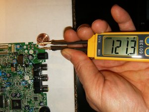
To test an SMD capacitor may be difficult to do with the bulky probes. One can either solder needles to the end of those probes, or invest in some smart tweezers. The preferred way would be using smart tweezers.
Block Image
Some capacitors do not require any test to determine failure. If a visual inspection of the capacitors reveal any sign of bulging tops, those need to be replaced. This is the most common failure in power supplies. When replacing a capacitor, it is of utmost importance to replace it with a capacitor of the same, or higher value. Never subsidize with a capacitor of lesser value.
Block Image
If the capacitor that is going to be replaced or checked, does not have any markings on it, a schematic will be necessary. The image below from here shows a few symbols for capacitors that are used on a schematic.
Block Image

We can move to INDUCTOR

Resistor

SMT Components

link for using multimeter


Resistor

The resistor is a passive electrical component to create resistance in the flow of electric current. In almost all electrical networks and electronic circuits they can be found. The resistance is measured in ohms. An ohm is the resistance that occurs when a current of one ampere passes through a resistor with a one volt drop across its terminals. The current is proportional to the voltage across the terminal ends.

Resistors are used for many purposes. A few examples include delimit electric current, voltage division, heat generation, matching and loading circuits, control gain, and fix time constants. They are commercially available with resistance values over a range of more than nine orders of magnitude. They can be used to as electric brakes to dissipate kinetic energy from trains, or be smaller than a square millimeter for electronics.

How To Test a Resistor


ResistorImage result for smd resistor
To check to see whether a resistor is good or not, we need to only perform one test and this is to check the resistor's resistance value, using the ohmmeter of a multimeter.

Test a Resistor with an Ohmmeter

Testing a Resistor with an ohmmeter is the best, easiest and most effective way to tell whether a resistor is good or not.
To set up for the check, we take the ohmmeter and place its probes across the leads of the resistor. The orientation doesn't matter, because resistance isn't polarized.
Image result for resistor colour coding

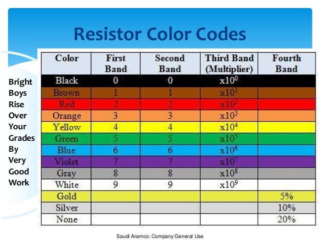
Resistor resistance test with an ohmmeter of a multimeterThe resistance that the ohmmeter reads should be close to the rated resistance of the resistor. For example, the following resistor above is a 1KΩ resistor with a tolerance rating of 5%. Therefore, the resistance of the resistor can vary between 950Ω and 1050Ω.
If the ohmmeter is reading in the value and tolerance range of the resistor, the resistor is good.
If the ohmmeter is reading (especially drastically) outside of this range, the resistor is defective and should be replaced.

How to Test whether a Resistor is Open

If a resistor is reading a very high resistance, above its rated value, it is open. It is defective and, thus, should be replaced.

How To Test whether a Resistor is Shorted

If a resistor is reading a very low resistance, near 0Ω, it's shorted internally. It is defective and, thus, should be replaced.
A resistance test is the only test that is needed to determine whether a resistor is good. If you want to examine more advanced features of a resistor, then additional tests may be necessary, but for all basic purposes, this test is sufficient for checking resistors.


Next we can see about capacitor

Introduction, Ohm's law and Types of current

Welcome to our Blog

Why I started this blog?

To make the people to learn about the electronics easily in a step by step process

Who am i?

I have a electronics service center in chennai. Where am an expert in repairing the mobiles, laptops and desktops, LCD and LCD tv service.


What you will see in this site?

We can see about ohm's law, Complete active and passive smt components and its testing with multimeter. And how to service your home appliances by yoursel. It will be very much useull to engineers also to understand about electronics.

LETS START----->


OHM'S law

Relationship between Voltage Current and Resistance.


ohms law

Lets imaging a water system

Current is the TANK that contains the WATER.

Voltage is the SIZE of the pipe connected to the tank.

Resistance is the TAP that connected at the end of the pipe.

I think you would have imagined.

Ohms LAW


By knowing any two values of the Voltage, Current or Resistance quantities we can use Ohms Law to find the third missing value. Ohms Law is used extensively in electronics formulas and calculations so it is “very important to understand and accurately remember these formulas”.

To find the Voltage, ( V )

                                            [ V = I x R ]      V (volts) = I (amps) x R (Ω)

To find the Current, ( I )

                                           [ I = V ÷ R ]      I (amps) = V (volts) ÷ R (Ω)

To find the Resistance, ( R )

                                          [ R = V ÷ I ]      R (Ω) = V (volts) ÷ I (amps)


Types of Current

Difference between AC and DC


In AC current the  shock will be less and it is used for electrical equipment purpose.

The AC is converted from DC because it can be stored and the shock will be 10 times higher than AC voltage. It is used for electronic purpose.


Let us move to SMT Components in my next blog.